In this tutorial I will show you a simple way to add additional texture to exported parts in Blender. I am not an expert. I am a tinkerer. Everything I know about Blender I have learned from Dr. Google and Professor YouTube. There are a million ways to add scratches, but this is one of the most basic ways... If you're really interested in this, I'd suggest searching for procedural scratches and mixing those techniques with what I'm showing here.
1. ENABLE NODE WRANGLER
Node Wrangler enables certain shortcuts to help with using nodes in Blender. Almost every tutorial I've ever seen on YouTube that touches on using nodes in Blender recommends turning it on.
Go to Edit > Preferences... > Add-ons > and search for "Node Wrangler." Then Click the checkbox to enable it.

2. OPEN YOUR WORKSPACE
Import your model. You will need a Shader Editor open. This is the window where we will work with the nodes. The simplest way to do this is to switch to the Shading tab. You will also need to switch your 3d viewport to Material Preview or Rendered because we will be manipulating the material nodes. Again, the Shading tab will automatically do this step for you. I also rearranged the windows on my Shading tab to make things easier to see for the tutorial.

3. THE BASE MATERIAL GROUP
All Mecabricks parts should share the same base material. However, due to differing generations of part designs, they may not all be the same, so you may need to do this process more than once. Click on a part and look for a green node called Base Material. These green nodes are groups. A number next to the shield in the group node indicates that that group is shared between that number of materials. If you click on that number and it goes away, then you will have made that group unique. Any changes you make to a unique node will not affect other materials. Any changes you make to a shared node will affect all the materials that share that group.
To edit the Base Material group, click on the icon in the upper right hand corner of the group node.

4. ADD A BUMP NODE
A bump node will take an image and translate that data into depth data for the Normal input on our Principled BSDF (Shader) node. The Normal input is used to fake geometry that actually isn't present in the 3D model. This is how Scrubs puts in the rough bits on sloped parts (available in Blender Lite) and also mold seams in the workshop and Blender Advanced.
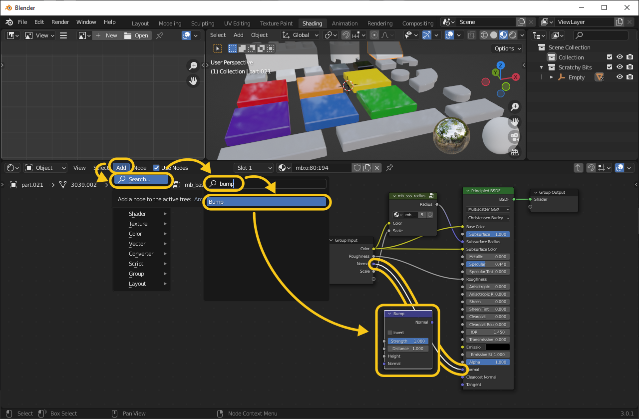
Now we will add in some scratches on top of the existing textures. In the Shader Editor window, click Add > Search > and search for "bump." Click on Bump and drag the node to the purple line going the the Normal input. When you hover the node over the line, the line will turn white. Drop the node here and Blender will connect it with what it thinks are the most appropriate options. In this case, Blender has guessed correctly. On this node, we will add to the existing normal data.
5. ADD A SCRATCH TEXTURE
The bump node makes dark parts of an image appear to be deeper into the object than light parts. So we will need a picture with dark scratches on a light background. Search for and download an image that has the density of scratches that you want (or create one yourself). If the image you use is backwards from this, you can use the Invert setting on the bump node to switch it. To add the image, we will use one of the keyboard shortcuts that we enabled with Node Wrangler. With only the bump node selected, hit [Ctrl + T]. This will add the nodes we need to get an image texture into the material. But this time Blender has guessed wrong on how to connect them. Change the output from the Texture Coordinate node from UV to Object. Then move the Bump node input that was in Strength to Height. Click on the Open button in the orange node and find your image file. You should have something like this:

6. FINE TUNE YOUR SCRATCH TEXTURE
Your scratches will probably look weird now. Part of the issue is that the texture is being projected directly from the side of your object. The texture has proper proportions on the front face, but there are streaks on the top and sides as this texture is getting dragged through the part.
To solve this, we can change the direction the image is being projected from. I used 45º in the X and Y Rotation fields in the Mapping node.

But it is still too small. To fix this we need to change the scale. An easy way to control the scale is to add a Value node. This will allow us to change the X, Y, and Z mapping scale values all at once with one number instead of having to do each axis separately. Add a Value node (Add > Search > Value) and connect it to the purple Scale input on the Mapping node. A value of 0.05-0.10 is a good starting point. This value will need to be very small, but not smaller than zero.

Now we have a good scratch projection, but you will notice that all similar parts will have the same pattern.

To solve this we will randomize the location. Add an Object Info node (Add > Search > Object Info) and connect its Random output to the Location input on the Mapping node. Now all of our parts don't look exactly the same.
Lastly, we need to adjust the strength of the scratches so they don't look all mangled. In the Bump node, adjust the Strength and Distance until you get something that you like... Generally, you'll want to adjust either or both of them down some.

WRAP-UP
Obviously this won't work perfectly with these exact settings for every part on every model. But hopefully you have learned the reason behind why we use certain nodes and why we set the values to what they are. Now you can experiment and come up with something awesome. A final note on the scratches image... I would go for something that has a large resolution (4000px or so) and a few scratches spread around the image. Then you can choose a very small scale for the value and you will have more variation among your parts.
Aaaand, if you want to try with the same image I used, here it is:

LEGO, le logo LEGO, la minifigurine et les configurations des briques et tenons sont des marques déposées de LEGO Group of Companies. ©2026 The LEGO Group.
Mecabricks, le logo Mecabricks et tout le contenu non couvert par les droits d'auteur du groupe LEGO sont, sauf indication contraire, ©2011-2026 Mecabricks.